3d Printer Runout Sensor
BrianSnelgrove - February 19, 2023Posted Under: Maker
What is filament runout?
Filament runout is just what it sounds like - your printer runs out of filament in the middle of a print and ruins the print. There is no good way to determine exactly where the printer ran out of filament and it is next to impossible to get the printer to start back up where it left off. If you have a filament runout sensor, the printer knows when it runs out and will immediately stop and wait for you to add more filament before it starts printing right where it left off.
More than just a runout sensor...
This design is more than just a runout sensor; it can also detect filament binds. I have had filament tangle up and bind, so the print head could not pull more filament. I have also seen some spools have the end of the filament attached to the center of the spool to bind up when the end of the spool is reached - more traditional runout sensors would not detect binds resulting in a failed print.
Let's get started!
I designed the files for this runout sensor using a free subscription to Onshape (model available here). Something like TinkerCad or any other CAD modeling software could be used, but I have had good luck with Onshape when designing more complex models. I don't have any formal training in CAD design; I am sure someone that knows what they are doing could do a better job refining the design. I have the STL files published on Thingiverse (STL available here). Go ahead and start printing the parts, there are only three and they should not take too long to print.
What other hardware is needed?
Most of this list is a copy/paste from the list I have on Thingiverse. I had a bunch of small screws, nuts, t-nuts, etc., leftover from my printer build so the only things I had to buy were the magnets, limit switches, and wire - your mileage may vary.
- 2x M5 screws - 10 mm
- 2x M5 t-nuts
- 2x M3 screws - 18 - 20 mm long, longer will not hurt anything
- 4x M3 screws - 10 - 12 mm long, longer will not hurt anything
- 2x M3 nuts and washers (or bed adjustment nuts)
- 2x limit switches - http://a.co/d/1JXC5kr from Amazon
- 4x magnets - 10mm x 3mm - http://a.co/d/10lAWrz from Amazon
- 1x Bowden tube and fitting - http://a.co/d/ax3PiVd from Amazon
- 1x epoxy to glue magnets
- 1x wire and connections
- 3mm tap (optional)
- 6mm tap (optional)
- soldering iron/flux/solder (optional)
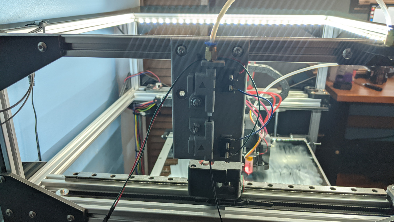
Assembly is pretty straightforward. Look at the picture at the top of this post to get an idea of what the completed project will look like. I mean, there are only 3 printed pieces and two limit switches... Again, most of this is copied/pasted from my Thingiverse post.
- Using an M3 tap, tap all 4 mounting holes in the limit switches - you may be able to cut threads with the screws but use a tap if you have access to one.
- Using an M6 tap to cut threads into the top of the sensor mount for the Bowden fitting- again, you may be able to use the fitting to cut the threads but use a tap if you have access to one.
- Push a short piece of Bowden tube (approximately 45mm) through the top (runout) guide, so the filament easily slides through. The tube should extend slightly beyond the top edge of the guide but not hit the Bowden mount.
- Glue magnets into the upper mount and top guide, so they oppose each other.
- Glue magnets into the lower mount and bottom guide, so they attract each other.
- Assemble the two guides onto the mount with the arrows all pointing in the direction of filament travel. Secure the guides with the longer M3 bolts and nuts. Use the bed leveling nuts (if you have them) to secure the guides. If you don't have bed leveling nuts, you can use a washer under a regular nut.
- Attach the two switches to the plate using the 4 shorter M3 screws. The top switch's arm should point up, and the arm of the bottom switch should point down.
- Wire the normally closed terminals of the limit switches in series and connect to your board/octopi/etc.
- Connect the two wires from the sensor to your printer board (you will have to determine the connectors to use)
What about the code?
Designing, printing, and assembling the limit switch was the easy part for me. After some trouble finding the g-code needed for it to work, I came up with this after some digging and experimenting.
Duet Configuration:
config.g (your command will be different depending on how you have the sensor wired):
; this is the older command for RepRap 2.x firmware
;M591 D0 P2 C3 S1 ; filament runout sensor
; if you have the newer RepRap 3.x firmware use this instead
; the only difference is the end stop name vs end stop number
M591 D0 P2 C"E0_STOP" S1 ; filament runout sensor
pause.g (the M109 command will need to be updated for your machine!):
; the following command work for RepRap 2.x and 3.x
M83 ; relative extruder moves
G91 ; relative positioning
G1 Z5 F360 ; lift Z by 5mm
G90 ; absolute positioning
G1 X280 Y280 F6000 ; go to the front left corner of the machine
M109 S30 ; turn off the hot end
M106 S0 ; turn off the part cooling fan
resume.g:
; the following commands work for RepRap 2.x and 3.x
; MAKE SURE YOU UPDATE THE HOT END TEMPERATURE BEFORE YOU RESUME PRINTING!!!!
G1 R1 X0 Y0 Z5 F3000 ; go to 5mm above the position of the last print move
G1 R1 X0 Y0 ; go back to the last print move
M83 ; relative extruder moves
M106 S0 ; restart the part cooling fan
Ocotprint (bonus!)
The following is how I had octoprint set up before I upgraded to a Duet. This is pulled from old notes I had; your mileage may vary. First, the g-code to move the hotend when the board detects a limit switch getting triggered:
G91 ; XYZ relative
M83 ; E relative
G1 Z+10 E-5 F4500 ; retract filament, move Z slightly upwards
M82 ; E absolute
G90 ; XYZ absolute
G1 X290 Y290 ; move to a safe rest position adjust this value!
{% snippet 'disable_hotends' %}
M106 S0 ; turn off the part cooling fan
Now for the g-code that is used to restart the print:
M83 ; relative extruder
M82 ; absolute E
G90 ; absolute XYZ
G92 E{{ pause_position.e }} ; reset E
G1 F4000 ;
G1 X{{ pause_position.x }} ; reset X
G1 Y{{ pause_position.y }} ; reset Y
G1 Z{{ pause_position.z }} ; reset Z
{% if pause_position.f is not none %}
G1 F{{ pause_position.f }} ;
{% endif %}
That looks simple enough, now what?
Give it a go and see if it works! There are a couple of short videos on YouTube that show how the sensors work, the first runout sensor was an initial design before the binding sensor was added, but the idea behind it is the same:
And the binding sensor - this is the same sensor I have had on my machine for a while, and it works great:
Items used in this guide:
- Duet 2 Wifi - Duet 2 printer controller board
- Folger Tech FT-5 - My most recent printer; with a few DIY upgrades, this thing is a beast!
- Onshape - If you dig long enough, you can find the link for a free account
- Thingiverse - A good place for finding/sharing STL files